Product Description
HF Repair kit:
Includes:
Item 3 • 037-075-8: Seal
Item 8 • HF-28: Bridge (was not original equipment on HC, HE & Early HF)
Item 9 • HC-5: Check Plate
Item 10 • HF-1: Gasket w/ Spring
Item 16 • H-27-A: Joker Valve
Item 19 • HE-8: Gasket
Item 25 • HF-26: Spring
Model HF: Pump Rebuild Instructions
Tools Required:
*Flat-blade screwdriver
*5/16 nut driver or socket wrench
*7/16 wrenches (2)
Instructions:
1. Close inlet and discharge seacocks.
2. Disconnect the inlet water hose, the pump-to-bowl hose and the discharge fitting from the pump.
3. Remove the three screws (three round head, flat blade screws) from the pump base and remove pump.
4. Make note of the orientation of the flapper gasket (HE-8).
5. Remove the cover from the rear of the pump (six screws, 5/16 nut driver).
6. Remove the gasket and spring (HF-1) and check plate (HC-5).
7. Inspect the cam assembly (HF-20) for wear, cracks and function. Check the finger for cracks at the joint. Rotate the handle to the "dry" position. Press on the back of the finger to check for a "spongy" feel. If spongy, remove, inspect and replace as needed.
8. Install bridge (HF-28) into center of chamber to support the gasket. Note: Some cylinders will have this already installed and can be left in place.
9. Install new check plate (HC-5) in upper chamber, flush with cylinder. This part must remain in position for a good seal to the gasket.
10. Install the new gasket (HF-1) with the weighted part down, facing the pump cylinder.
Note: Screw pattern only allows this to be installed one way.
11. Install the spring to the gasket flap. The small end of the spring attaches by friction to the center of the flap.
12. Polish the sealing surface of the cover with a fine grit emery paper to ensure a smooth surface. Clean any grit/debris from the cover before installing.
13. Insert and start the six screws holding the cover in place. When all six are started, snug them down to ensure a good seal. Do not over-tighten the screws as this will distort the gasket and not allow the pump to prime.
14. Test the unit by rotating the selector handle to the full travel several times. This will set and break-in the gasket.
15. Install a temporary hose to the water inlet fitting, place opposite end into a bucket of water and test the prime function. The unit should draw water after 2-3 pumps. If not, check and repeat Steps 7-12. Remove temporary hose upon test completion.
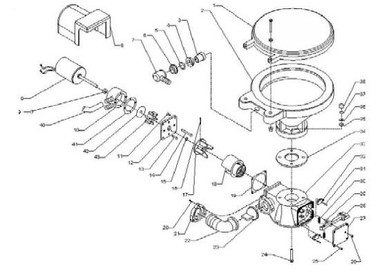
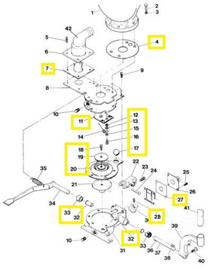
16. Install the joker valve (H-27-A) with the "slit" parallel to the pump cylinder (see exploded parts view of HF Service Information).
17. Install the discharge elbow over the joker valve and secure the two bolts. Do not over-tighten.
18. Place the new gasket (HE-8) onto the bask. The weight must face up. Mount the pump to the base with the three screws from Step 3. Do not over-tighten these screws or the cylinder may crack.
19. Re-install the pump-to-bowl hose, the water inlet hose and secure all hose clamps that may have been loosened.
20. Open both inlet and discharge seacocks.
21. Test for proper operation.
Warning: This item may contain ingredients that are listed under P65warnings.ca.gov